
Circuit breakers rely on electromagnetic actuation to open and close their contacts on command, and the AC 220V 56 Ohm Closing and Tripping Coil serves as the electromechanical interface between the control system and the breaker mechanism. This article examines how the coil functions within a circuit breaker operating mechanism, the significance of its 56-ohm resistance value in the 220V control circuit, material construction requirements for reliable service, and the maintenance practices that ensure consistent operation.
▸ Table of Contents — Click any topic to jump directly
- What Is a Closing and Tripping Coil?
- How the Coil Operates Within the Breaker Mechanism
- The Significance of 56 Ohm Resistance
- Coil Construction and Material Requirements
- Applications in Circuit Breaker Systems
- Maintenance, Testing, and Failure Prevention
- Technical Specifications Reference
- Frequently Asked Questions
What Is a Closing and Tripping Coil?
A closing coil and a tripping coil are electromagnetic actuators installed inside a circuit breaker operating mechanism. The closing coil, when energised, drives the mechanism to close the breaker contacts and establish the electrical connection. The tripping coil performs the opposite action: when energised, it releases the latch that holds the contacts closed, allowing the spring mechanism to open the breaker.
Both coils share the same fundamental construction—a copper wire winding around a movable iron core—but they act on different latches within the mechanism. The closing coil extends a plunger that engages the closing latch, while the tripping coil extends a plunger that releases the trip latch. Once the coil is de-energised, a return spring retracts the plunger to its rest position, ready for the next operation.
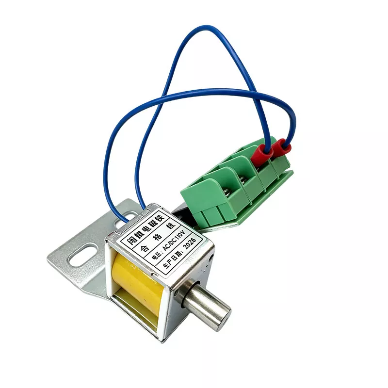
The AC 220V 56 Ohm Closing and Tripping Coil is specified for control circuits operating at 220 volts alternating current, with a nominal winding resistance of 56 ohms. This resistance value determines the current drawn by the coil during energisation, which in turn affects the magnetic force available to actuate the mechanism and the thermal load on the winding.
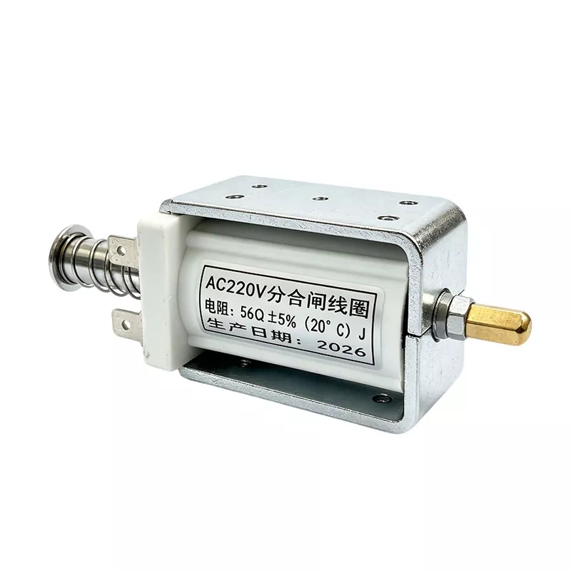
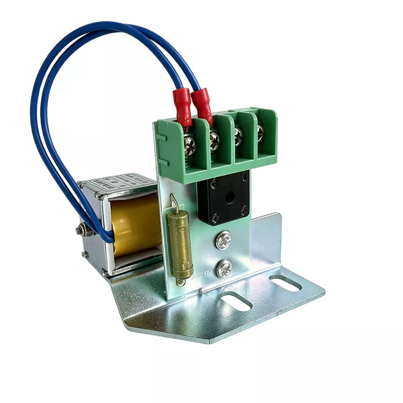
AC 220V 56 Ohm closing and tripping coil configured for circuit breaker operating mechanisms.
Closing Coil
Energised to drive the mechanism toward the closed position, establishing electrical continuity through the breaker contacts.
Tripping Coil
Energised to release the latch holding the contacts closed, allowing the spring mechanism to open the circuit.
How the Coil Operates Within the Breaker Mechanism
The operating principle of both coils is electromagnetic induction. When current flows through the coil winding, a magnetic field is generated around the core. This field exerts a force on the movable iron plunger, driving it forward into the latch mechanism. The plunger strikes the latch, either engaging it (closing) or releasing it (tripping), and the breaker mechanism completes the action.
A critical characteristic of these coils is their short-time duty rating. They are designed for brief energisation only—typically less than one second—and cannot withstand continuous energisation without overheating. The auxiliary contacts of the circuit breaker are arranged to interrupt the coil circuit as soon as the breaker completes its travel. This means the coil is de-energised automatically once the operation is complete.
If the auxiliary contact fails to open, or if the mechanical mechanism jams, the coil remains energised and rapidly overheats. This is the most common cause of coil burnout in field service, and it underscores the importance of proper auxiliary contact adjustment during installation and maintenance.
The Significance of 56 Ohm Resistance
The resistance of the coil winding is not an arbitrary value—it is determined by the electrical and magnetic requirements of the application. At 220V AC, a 56-ohm coil draws approximately 3.93 amperes of current during energisation. This current level produces the magnetic force necessary to actuate the latch mechanism reliably.
| Parameter | Value | Notes |
|---|---|---|
| Rated Voltage | AC 220V | Standard control circuit voltage |
| Nominal Resistance | 56 Ohm | Winding DC resistance |
| Approximate Current Draw | 3.93 A | At rated voltage, calculated from V/R |
| Duty Rating | Short-time | Typically less than 1 second |
| Operating Voltage Range | 85% – 110% of rated | Standard for closing coils |
The relationship between resistance and current is governed by Ohm's law. A lower resistance coil draws more current and produces a stronger magnetic force, but also generates more heat. A higher resistance coil draws less current, produces less force, and may fail to operate the latch reliably. The 56-ohm value represents a carefully balanced point that provides sufficient actuation force within the thermal limits of the winding.
When testing a coil in the field, resistance measurement is a primary diagnostic indicator. A reading that deviates significantly from the nominal 56 ohms suggests either a shorted turn (reading lower than expected) or a partially open winding (reading higher than expected). Either condition warrants replacement of the coil before it fails in service.
Coil Construction and Material Requirements
The reliability of a closing or tripping coil depends on the quality of its constituent materials and the precision of its manufacture. Several construction factors determine whether the coil will perform consistently over thousands of operations.
- Copper wire with controlled diameter and consistent insulation thickness
- Winding tension maintained within specification to prevent loose turns
- Iron core with appropriate magnetic permeability and smooth surface finish
- Return spring matched to the plunger mass and required retraction force
- Terminal connections capable of withstanding vibration without loosening
- Insulation rated for the temperature rise encountered during short-time duty
The coil is typically wound as a cylindrical solenoid with an open centre through which the plunger moves. The winding must be tightly wound and securely varnished or encapsulated to prevent movement under the electromagnetic forces generated during operation. Loose turns would rub against each other, eventually wearing through the insulation and creating a short circuit.
Applications in Circuit Breaker Systems
Closing and tripping coils are used across a broad spectrum of circuit breaker types and voltage levels. The following applications represent the primary settings where the AC 220V coil configuration is deployed.
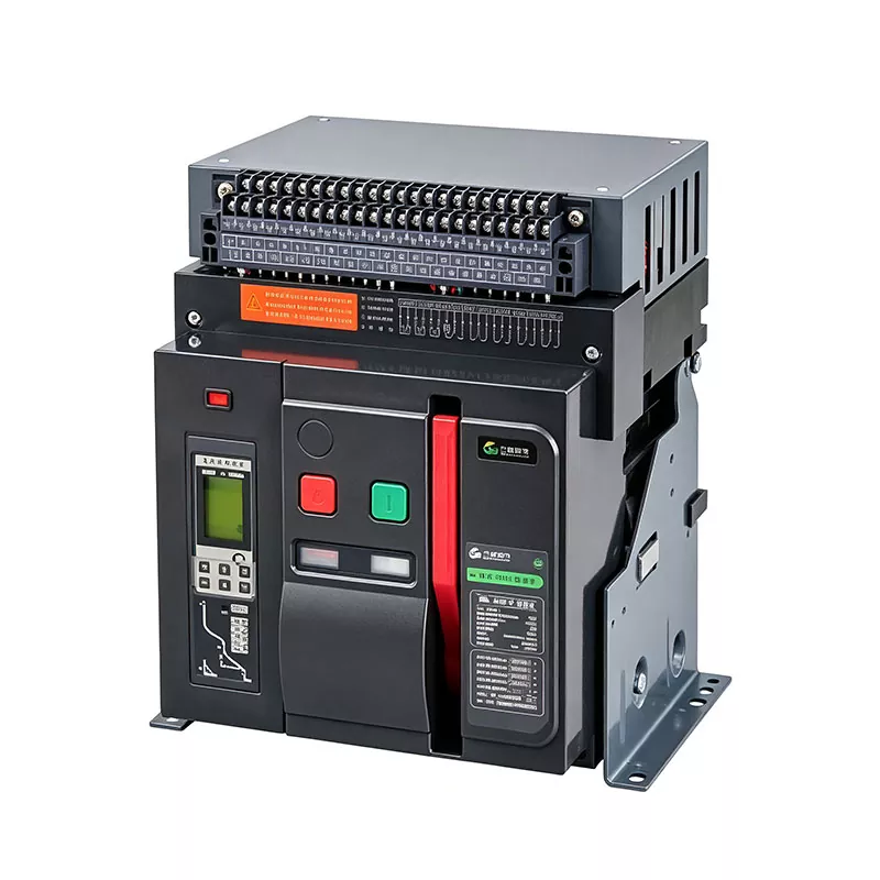
- Low-voltage air circuit breakers (ACBs) in distribution panels and switchboards
- Moulded case circuit breakers (MCCBs) equipped with shunt trip or closing accessories
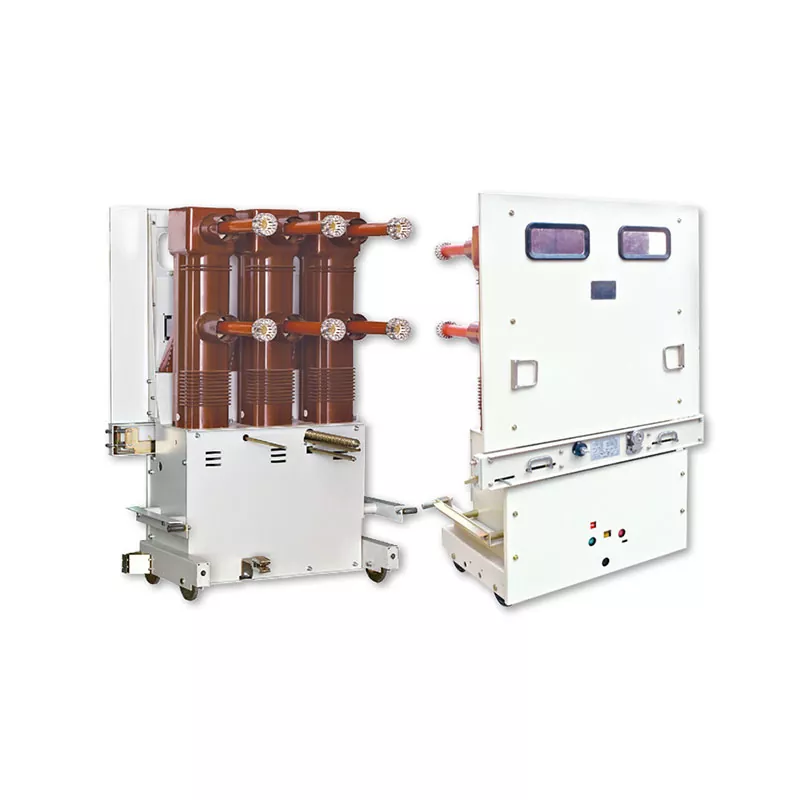
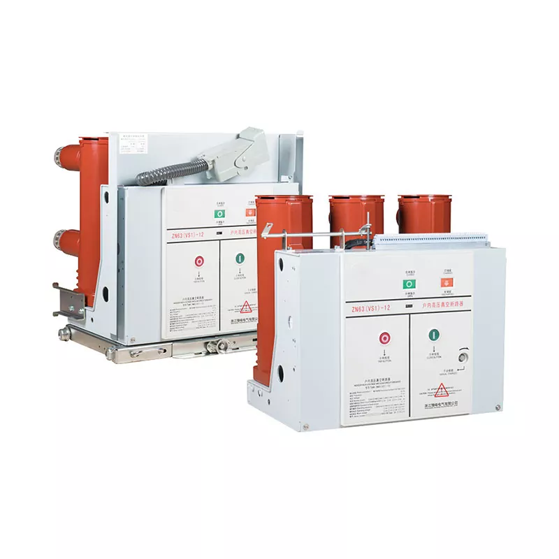
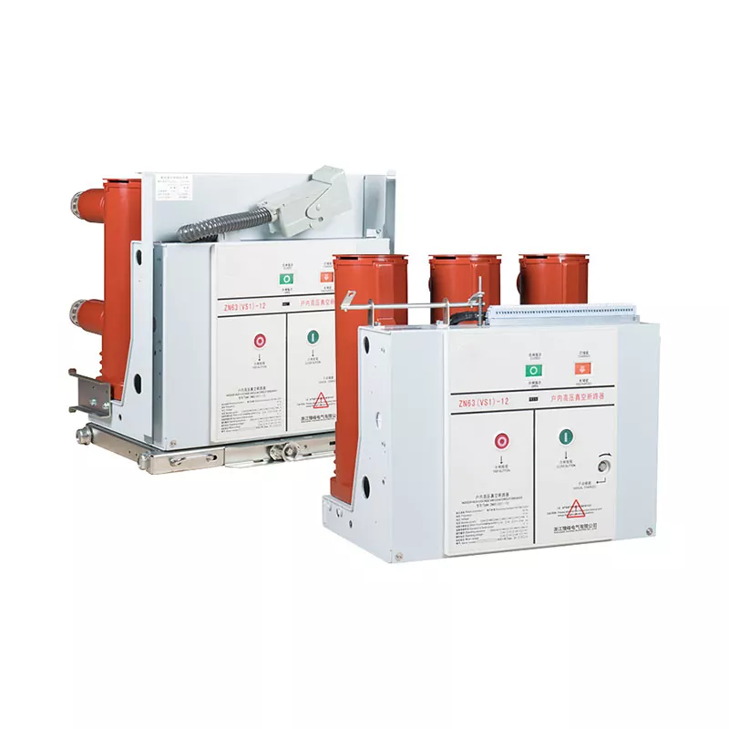
- Vacuum circuit breakers in medium-voltage switchgear for industrial and utility substations
- Remote-controlled breakers in automated power distribution systems
- Generator control panels where automatic synchronisation requires precise breaker timing
- Motor control centres with remote trip functionality for emergency shutdown
In automated systems, the closing coil receives its command from a supervisory control and data acquisition (SCADA) system or a programmable logic controller. The tripping coil may be commanded by a protection relay that detects an overcurrent, earth fault, or other abnormal condition. In both cases, the coil is the final electromechanical link in the control chain—the component that translates an electrical signal into physical motion.
Maintenance, Testing, and Failure Prevention
Regular testing and inspection of closing and tripping coils is essential for maintaining the reliability of circuit breaker protection systems. The following practices are recommended based on industry standards including IEEE C37.09 and IEC 62271-100.
- Measure DC resistance of the coil winding and compare against the nominal 56-ohm value. Deviations exceeding ±5% indicate a potential fault.
- Inspect the coil terminals for corrosion, loosening, or signs of overheating.
- Check the iron core and plunger for rust, scoring, or mechanical binding that could prevent full travel.
- Verify that the auxiliary contact opens correctly to de-energise the coil after each operation.
- Perform functional tests at minimum pickup voltage to confirm the coil actuates the mechanism reliably.
- Record all measurements and compare against baseline values to detect gradual degradation trends.
The most common causes of coil failure are prolonged energisation due to auxiliary contact malfunction, mechanical binding that prevents the plunger from completing its travel, and corrosion of the iron core in damp environments. Regular inspection of the operating mechanism and the coil itself can identify these conditions before they lead to failure.
Signs Requiring Immediate Replacement
Certain conditions indicate that a coil should be replaced without delay, regardless of its measured resistance.
- Visible charring, discolouration, or insulation damage on the winding
- Rusted or pitted iron core that impedes plunger movement
- Resistance reading outside the ±5% tolerance band
- Evidence of arcing or pitting at the terminals
- Failed functional test at rated control voltage
- Physical damage to the coil former or terminal block
Technical Specifications Reference
| Parameter | Specification | Notes |
|---|---|---|
| Product Type | Closing and tripping coil | Dual function electromagnetic actuator |
| Rated Voltage | AC 220V | Standard control circuit voltage |
| Winding Resistance | 56 Ohm | Nominal DC resistance |
| Current Draw | Approximately 3.93 A | At 220V AC, calculated |
| Duty Cycle | Short-time | Typically less than 1 second energisation |
| Operating Range | 85% – 110% of rated voltage | Standard for closing coils |
| Core Material | Soft iron or silicon steel | High magnetic permeability |
| Winding Material | Copper wire | Enamelled insulation |
| Compatible Breakers | ACB, MCCB, VCB | With matching control circuit |
| Test Standard | IEEE C37.09, IEC 62271-100 | Resistance measurement guidance |
These values serve as a specification baseline. Final selection should confirm compatibility with the specific breaker model, control circuit voltage, and operating mechanism design.
Frequently Asked Questions
What is the difference between a closing coil and a tripping coil?
A closing coil drives the mechanism to close the breaker contacts when energised. A tripping coil releases the latch that holds the contacts closed, allowing the spring mechanism to open the circuit. Both are short-time duty solenoids that operate on the same electromagnetic principle but act on different latches within the operating mechanism.
Why is the coil resistance specified as 56 ohms?
The 56-ohm resistance determines the current drawn from the 220V control circuit, which in turn determines the magnetic force available to actuate the mechanism. A lower resistance would draw more current and produce more force but also generate more heat. A higher resistance would reduce the actuation force. The 56-ohm value represents a balanced point that provides reliable operation within the thermal limits of the winding.
What causes a closing or tripping coil to burn out?
The most common cause is prolonged energisation due to a malfunctioning auxiliary contact that fails to interrupt the coil circuit after the breaker completes its operation. Other causes include mechanical binding that prevents the plunger from completing its travel, corrosion of the iron core, and degradation of the winding insulation over time.
How often should closing and tripping coils be tested?
Testing intervals depend on the operating cycle frequency and environmental conditions. Routine maintenance schedules typically include resistance measurement annually or after a specified number of operations. Coils in high-cycle applications or corrosive environments may require more frequent inspection.
Can a coil with the wrong resistance value be used as a replacement?
No. The coil resistance must match the control circuit design. A coil with lower resistance will draw excessive current and may overheat or damage the control circuit. A coil with higher resistance may not produce sufficient magnetic force to actuate the mechanism reliably, leading to breaker failure to operate.
What should be checked when installing a replacement coil?
Verify that the coil resistance matches the specified value, confirm the plunger travels freely through the core, check that the auxiliary contact will interrupt the coil circuit after operation, and ensure all terminal connections are tight. A functional test at rated control voltage should be performed before returning the breaker to service.
For maintenance engineers and switchgear specifiers, the AC 220V 56 Ohm Closing and Tripping Coil is a critical component in the circuit breaker control chain. Confirming voltage compatibility, resistance value, and mechanical fit before installation ensures reliable operation across the full service life of the breaker.
Dongfa manufactures closing and tripping coils for circuit breaker operating mechanisms from its production facility in Yueqing, Wenzhou, Zhejiang Province, supplying switchgear manufacturers and utilities across domestic and international markets.